Rapporto impulsi attuatore e movimento in gradi del Polarmount, quesito matematico

@a33

certe volte è difficile capirsi anche quando si parla la stessa lingua...

evidentemente il traduttore ti ha portato sulla strada sbagliata fin dalla prima volta che ho accennato a questo "falso problema".

Una volta per tutte spacifico che:

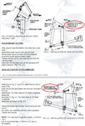
1) Il polarmount Channel Master in combinazione con l'attuatore da 18" funziona perfettamente e non mi da nessun problema, sono molto soddisfatto di questo da oltre 30 anni.

2) Non ha necessità di nessuna modifica.

3) Generalmente i polarmount con attuatore a differenza dei motori HH hanno dei limiti di escursione Est - Ovest diversi e sono limitati nel coprire l'intero arco satellitare, (anche in funzione della propria longitudine) è una loro caratteristica/limite.

Quindi quanto è successo è perché si è cercato di andare oltre il limite consentito, limite che cambia in funzione della propria longitudine.

Quando questo accade e la parabola "cade", nel mio caso tutta ad ovest, non è possibile riportarla allo stato funzionale, non perchè l'attuatore non ha la forza per farlo (anche se potrebbe presentarsi questa condizione) ma per alltri motivi:

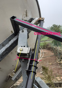
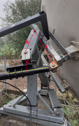
Quando la parabola parte dai 63°E arriva a 45°W l'attuatore è aperto quasi per tutta la sua lunghezza, può andare avanti solo un altro po'. se ci si spinge oltre i 45°W---> 50°W---> 55°W in un punto imprecisato, l'attuatore si ferma perchè ha raggiunto il limite della sua estensione, ma la parabola con il suo peso continua la sua corsa verso ovest trascinandosi dietro l'intero attuatore come fosse un pezzo unico e non estensiblile... quindi il percorso dai 55°W ai 85°W (numeri ipotizzati) viene fatto senza l'ausilio dell'attuatore ma per la forza di gravità, come una automobile in discesa non ha bisogno del motore, se non c'è un freno scende lo stesso...

Questo percorso dai 55°W ai 85°W (numeri ipotizzati) non viene recepito dal posizionatore perché viene effettuato con attuatore bloccato alla sua massima estensione sia elettricamente che meccanicamente, quindi il reed non fornisce impulsi e non viene conteggiato nulla...

Quindi, quando la parabola è a 85°W dando tensione al motore (in maniera autonoma perchè il posizionatore potrebbe rifiutarsi di farlo causa switch fine corsa e nessaggi di errore) l'attuatore ritraendosi non potrebbe mai riportarla a 63°E perché il percorso è troppo lungo rispetto alla corsa dell'attuatore, perquesto ci vuole l'intervento manuale sul posto, e cioè la parabola andrà riportata su a mano...

In più ora non ricordo bene perché accaduto 29 anni fa, che il sistema di leve potrebbe assumere una posizione per cui l'attuatore potrebbe non essere più in grado di "riportare su il tutto"

Ricordo bene, che comunque sono dovuto intervenire sul posto con una batteria 12V 7A per alimentare l'attuatore autonomamente.

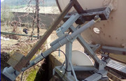
Ho prima riportato su la parabola a mano con la forza delle braccia fino al punto in cui inizia la caduta spontanea, poi ho dato tensione all'attuatore per consentirgli di ritornare a 63°E ( attuatore tutto chiuso).


Spero sia tutto chiaro, più di così non so che fare.

Buona Domenica.

Translation.

sometimes it's difficult to understand each other even when you speak the same language...

evidently the translator led you down the wrong path from the first time I mentioned this "false problem".

Once and for all it is clear that:

1) Channel Master polarmount in combination with the 18" actuator works perfectly and does not give me any problems, I have been very satisfied with this for over 30 years.

2) It does not need any modification.

3)Generally, polarmounts with actuators, unlike HH motors, have different East - West excursion limits, and are limited in covering the entire satellite arc, also depending on their longitude, but this is normal and is one of their characteristics.

So what happened is because we tried to go beyond the permitted limit, a limit that changes depending on one's longitude.

When this happens and the dish "falls", in my case all the way to the west, it is not possible to bring it back to its functional state, not because the actuator does not have the strength to do it (although this condition could arise) but for other reasons:

When the dish starts from 63°E reaches 45°W the actuator is open almost along its entire length, it can only go forward a little longer. if you go beyond 45°W---> 50°W---> 55°W at an unspecified point, the actuator stops because it has reached the limit of its extension, but the dish with its weight continues its travel towards the west dragging the entire actuator behind it as if it were a single piece and not extensible... therefore the path from 55°W to 85°W (hypothesized numbers) is done without the aid of the actuator but by force of gravity, like a car going downhill it doesn't need the engine, if there isn't a brake it goes down anyway...

This path from 55°W to 85°W (hypothesized numbers) is not received by the positioner because it is carried out with the actuator blocked at its maximum extension both electrically and mechanically, therefore the reed sensor does not provide pulses and nothing is counted...

Therefore, when the dish is at 85°W, giving voltage to the motor of the actuator, by retracting, could never bring it back to 63°E because the path is too long compared to the stroke of the actuator, which requires manual intervention on site, the dish will have to be brought back by hand.

Furthermore, now I don't remember well because it happened 29 years ago, that the lever system could assume a position whereby the actuator could no longer be able to "bring everything back up"

I remember well, that in any case I had to intervene on site with a 12V 7A battery to power the actuator.

First brought the dish up by hand with the strength of my arms and hands to the point where the spontaneous fall began,
then I powered the actuator with 12V DC battery to allow it to return to 63°E (actuator fully closed).

I hope everything is clear, I don't know what to do beyond that.

Happy Sunday
 
Ultima modifica:
Quindi, per tutto il tempo in cui hai cercato di descrivere che il tuo piatto si era "afflosciato", ho riconosciuto questa come una possibile causa, ma ovviamente non conoscevi il fenomeno.
Al punto 84 ho descritto brevemente cosa succede in una situazione di flopping.
E sì, la "teoria" ne sa qualcosa. Non dipende dalla longitudine di una persona, come scrivi tu, ma dalla montatura. Dipende da dove si imposta l'intervallo 0-180 gradi per l'angolo T-A-BB (senza includere la lunghezza B-BB; per semplificare le cose al momento), che si può definire liberamente su tutto l'arco (anche sulla parte invisibile dell'arco!).

Inoltre: Buona domenica!

Tradotto da:

So, all the time you tried to describe that your dish had 'flopped', I recognized that as a possible cause, but obviously you didn't know the phenomenon.
I described briefly what happens in a flopping situation in #84.
And yes, "theory" knows about that. It is not dependent on someone's longitude, as you write, but on the mount setup. It is dependent on where you set your 0-180 degree range for the T-A-BB angle (not including the B-BB length; to simplify things at the moment), which you can freely define all over the arc (even to the invisible part of the arc!).

Also: Happy sunday!

Ciao,
A33
 
Quindi, per tutto il tempo in cui hai cercato di descrivere che il tuo piatto si era "afflosciato", ho riconosciuto questa come una possibile causa
Al punto 84 ho descritto brevemente cosa succede in una situazione di flopping.[/QUOTE]

E io al punto # 88 ti ho risposto:

@a33

finalmente inziamo a capirci, si è più o meno quello è che hai scritto, c'è voluto il mio intervento manuale per riportare su la parabola altrimenti come avevo già scritto sarebbe stato impossibile farlo con l'attuatore.

Il polarmount non l'ho progettato io ma è originale Channel Master, quel problema non lo giudico un errore di progettazione ma solo un limite da non superare, il polarmount potra coprire un determinato arco non di più, questo è il limite che differenzia i polarmount dai motori HH.

Si può fare di meglio di come hanno progettato quello della Channel Master? forse si ma per il momento a me va bene così
Ammettendo implicitamente che il problema (che per me non è un problema) può dipendere dal "disegno" del polarmount.

ma ovviamente non conoscevi il fenomeno.
Il fenomeno l'ho conosciuto con la pratica, perché non c'è scritto nulla al riguardo nel manuale del polarmount, nessuna avvertenza... in più quando parlo di Polarmount mi riferisco sempre alla geometria del Channel Master, anche se ovviamente il principio di funzionamento è lo stesso per qualsiasi polarmount, anche nelle istruzioni generiche di messa a punto di un qualsiasi polarmount non si cita mai questa possibilità, e non citarla non vuol dire logicamente, che non esiste.

Inoltre anche alcune traduzioni dall' inglese all' italiano specialmente quando si usano termini tecnici non sempre sono comprensibili al 100%per cuiin alcuni casi non comprendo bene quello che scrivi.
All'inizio non sapevo il nome in inglese di quello che tu hai chiamato BB ... che è il punto dove c'è lo snodo dell'attuatore o uniball, ma uniball è anche all'estremità dell'attuatore... quindi si poteva creare un altro equivoco...

Però secondo me c'entra anche la longitudine...

Se sono a Roma o a Madrid non è la stessa cosa... per raggiungere i 45°W e andare oltre, sia l'attuatore che il polarmount a Madrid dovranno "percorrere meno strada" per spostare la parabola verso ovest visto che il satellite centrale di riferimento a Madrid non è Hotbird 13°E ma dovrebbe essere uno che si trova a 3°E circa. (posizione centrale del polarmount).

In più nelle istruzioni, l'installazione dell'attuatore cambia anche in funzione della longitudine.


comunque io a quest' ora inizio a dare i numeri e non riesco a ragionare con lucidità :D...
 
Ultima modifica:
Sì, alla fine abbiamo superato i problemi di traduzione e di comunicazione (solo) scritta. Se fossimo stati entrambi al sito della parabola per spiegare il problema, avremmo capito in 5 minuti!

E in effetti, quando non si effettua una modifica alla montatura polare, dipende dalla longitudine, dove (in quale posizione del satellite) inizia il rischio di fluttuazione.
Per montare l'attuatore a est o a ovest della montatura, Titanium (USA) usa la regola di scegliere il lato in cui il satellite "più estremo" ha la minore elevazione. (Il satellite più estremo che si vuole o si può ricevere, a est o a ovest).
Il motivo principale è che la potenza maggiore dell'attuatore si trova sempre sul lato retratto, dove può lavorare meglio contro la gravità. Inoltre, se non si cambia la configurazione della montatura/attuatore Channel Master che ha il BB (Bottom Bolt) esattamente a nord, si riduce il rischio di fluttuare dall'altro lato della montatura.

Ho ritrovato una bella figura esplicativa del funzionamento di un attuatore, si trova sotto "actuatormath" su questo sito web: http://www.redrok.com/actuator.htm
Si può vedere dove sono T, A, BB e B.
Si possono vedere i limiti consigliati per il fluttuare, a +75 e -75 gradi di rotazione.
Si può notare che il movimento riguarda i gradi di rotazione intorno ad A, e che non importa dove si trovi il punto sud.
Si può notare che la massima precisione e la massima potenza dell'attuatore si trovano a circa -20 gradi nella figura (a causa del rapporto di lunghezza del braccio, di cui ho scritto prima, e della distanza B-BB).
(N.B. Uso l'intervallo da 0 a 180 gradi, invece di -90 a +90. Questo perché il punto a metà strada tra -90 e +90 non ha alcuna importanza per la configurazione).

Forse questa figura aiuta un po' a capire le impostazioni della montatura.

Tradotto da:


Yes, in the end we overcame the translation problems and the problems of (just) written communication. Had we both been at the dish site to explain what was the matter, we'd have understood in 5 minutes!

And indeed, when you don't make a change on the polar mount, it depends on your longitude, where (at what satellite position) the risk of flopping begins.
For mounting the actuator east or west of the mount, Titanium (USA) uses the rule to choose the side where the 'most extreme' satellite has the lowest elevation. (The most extreme satellite that you want to, or can, receive; east or west).
The main reason for that is that the most actuator power is always at the retracted side; so there it can work better against the gravity. And indeed when you don't change the Channel Master mount/actuator setup which has BB (Bottom Bolt) exactly north, this would diminish the risk of flopping at the other side of the mount.

I refound a neat explanation figure for the working of an actuator, it is under "actuatormath" on this website: http://www.redrok.com/actuator.htm
You can see where T, A, BB and B are.
You can see the advised boundaries for flopping, at +75 and -75 rotational degree.
You can see that the movement concerns rotational degree around A, and that it doesn't matter where due south is.
You can see that maximum actuator precision and maximum actuator power would be at about -20 degree in the picture (due to the arm length ratio, I wrote about earlier, and distance B-BB).
(NB I use the range 0 to 180 degree, instead of -90 to +90. That is because the point halfway between -90 and +90 is of no real significance for the setup.)

Maybe this figure helps a bit, for understanding mount setups.

Ciao,
A33
 
Con l'aiuto di un amico ho creato una tabella Excel per calcolare l'indice di ogni posizione SAT:
Deve avere
-coordinate di latitudine e longitudine
-le dimensioni del triangolo del sistema di cilindri
-il numero di impulsi per inch o mm del cilindro.
Lo uso da molto tempo e per diverse persone e dà risultati molto precisi.
Per il problema del cilindro che fa forza agli estremi, ho realizzato un contrappeso e ho realizzato una parte che separa il punto di fissaggio del cilindro (vedi foto).
Idealmente A dovrebbe essere uguale a B + C e A = metà della corsa del cilindro ex 36 pollici = 90 cm A = 45 cm.

Avec l’aide d’un ami j’ai créé un tableau Excel pour calculer l’indice de chaque position SAT :
Il faut avoir
-les coordonnées latitude, longitude
-les côtes du triangle du système de vérin
-le nombre de pulses par inch ou mm du vérin.
Je l’utilise depuis longtemps et pour plusieurs personnes et ça donne des résultats très précis.
Pour le problème de vérin qui force sur les extrêmes, j’ai fait un contrepoids et j’ai fait une pièce qui écarte le point de fixation du vérin (voir photos).
Dans l’idéal A doit être égal à B +C et A = à la moitié de la course du vérin ex 36 pouces = 90cm A=45cm.

With the help of a friend I created an Excel table to calculate the index of each SAT position:
Must have
-latitude, longitude coordinates
-the dimensions of the triangle of the cylinder system
-the number of pulses per inch or mm of the cylinder.
I have used it for a long time and for several people and it gives very precise results.
For the problem of the cylinder which forces on the extremes, I made a counterweight and I made a part which separates the fixing point of the cylinder (see photos).
Ideally A should be equal to B +C and A = half the stroke of the cylinder ex 36 inches = 90cm A=45cm.


Ultima modifica:
@Dreambox:

So che sei affezionato alla tua configurazione.
Ma, come ben sai, non sono d'accordo con la tua idea di definire A = B+C una configurazione ideale. Vedi https://satellites.co.uk/forums/threads/my-channel-master-1-8-project.180003/page-25#post-1128312
Temo di non ricordare se da qualche parte hai fornito le tue argomentazioni, perché pensi che sia più ideale di A > B+C?

In effetti, mi piace che la distanza C (nei miei termini: distanza B-BB) sia più grande dei soliti morsetti dell'attuatore, per avere meno possibilità di fluttuare sul lato estratto dell'attuatore. (Ne ho parlato in questo thread).


Per tutti coloro che sono interessati a sapere come ho sviluppato il mio pensiero sull'argomento, con qualche prova ed errore, si vedano i link riassunti in questo post: https://rickcaylor.websitetoolbox.com/post/show_single_post?pid=1333200747&postcount=12&forum=409261


Tradotto da:

@Dreambox:

I know you are fond of your setup.
But, as you well know, I don't agree to your idea of calling A = B+C an ideal setup. See https://satellites.co.uk/forums/threads/my-channel-master-1-8-project.180003/page-25#post-1128312
I'm afraid I don't remember if you somewhere gave your arguments, why you think it would be more ideal than A > B+C?

Though in fact, I do like that you have distance C (in my terms: distance B-BB) larger than the usual actuator clamps, to have less chance of flopping at the extracted side of the actuator. (I did mention it in this thread.)


For all those who are interested in how I developed my thoughts on the subject, with some trial and error, see the links summed up in this post: https://rickcaylor.websitetoolbox.com/post/show_single_post?pid=1333200747&postcount=12&forum=409261

Ciao,
A33
 
Naturalmente diverse soluzioni possono essere interessanti!
Se A > B+C allora la parte posteriore del cilindro sale verso il cielo (verso ovest nel mio caso) e può ricevere acqua attraverso il foro sul fondo del coperchio.
A non deve essere inferiore a B+C perché (ad ovest) il cilindro non sarà in grado di gestire la posizione massima.
Se A è molto più grande di B+C allora è necessario un cilindro più lungo e ho già solo 45 cm per A con un cilindro da 36 inch

Of course several solutions can be interesting!
If A > B+C then the rear of the cylinder goes up towards the sky (to the west in my case) and can receive water through the hole at the bottom of the cover.
A must not be less than B+C because (to the west) the cylinder will not be able to manage the maximum position.
If A is much greater than B+C then a longer cylinder is needed and I already only have 45cm for A with a 36 inch
 
Se A è molto più grande di B+C allora è necessario un cilindro più lungo e ho già solo 45 cm per A con un cilindro da 36 inch

If A is much greater than B+C then a longer cylinder is needed and I already only have 45cm for A with a 36 inch

Un attuatore più lungo è (in teoria) necessario solo se (nei miei termini): T-A è più di 3 volte più lungo di A-BB.
(Nei vostri termini: se A > 3*B).
In quella zona di T-A < 3*A-BB, è solo la posizione del morsetto dell'attuatore sul tubo dell'attuatore che si "sposta" verso la base del tubo dell'attuatore.
Vedere il mio riassunto in questo post: https://www.digital-forum.it/showth...o-matematico&p=7781770&viewfull=1#post7781770

Penso che T-A = 2,5 * A-BB in pratica non sia un problema.
Poiché la lunghezza massima della corsa totale (per 0-180 gradi) non cambia, non è necessario un attuatore più lungo.
Infatti, ho calcolato che se ora A=45, B=30, C=15, la lunghezza massima della corsa totale per 0-180 gradi è di 73,5.
Con A=90, B=30, C=15, la lunghezza massima della corsa totale per 0-180 gradi sarebbe di soli 61! Quindi si potrebbe utilizzare un attuatore più corto!

L'effetto benefico di una distanza T-A sempre più lunga, tuttavia, diventa sempre più piccolo:
Ho calcolato che la "zona di massima precisione" si sposta (considerando B-BB come zero, per semplicità):
da zero gradi (da 0 a 180 ), in corrispondenza della zona di massimo arretramento dell'attuatore, quando il rapporto è di 1 : 1;
a 48,2 gradi (da 0 a 180 ) di rotazione dalla zona di massima ritrazione, quando il rapporto è 1 : 1,5;
a 60,0 gradi (da 0 a 180) di rotazione dalla zona di massima retrazione, quando il rapporto è 1 : 2;
a 70,5 gradi (da 0 a 180) di rotazione dalla zona di massima retrazione, quando il rapporto è 1 : 3.


Tradotto da:

A longer actuator is (in theory) only needed if (in my terms): T-A is more than 3 times longer than A-BB.
(In your terms: if A > 3*B).
In that zone of T-A < 3*A-BB, it's just the location of the actuator clamp on the actuator tube, that 'moves' towards the base of the actuator tube.
See my summing up in this post: https://www.digital-forum.it/showth...o-matematico&p=7781770&viewfull=1#post7781770

I would think T-A = 2,5 * A-BB would in practice be no problem at all.
Because the maximum total stroke length (for 0-180 degrees) does not change, a longer actuator is not needed.
In fact, I calculated: when you have now A=45, B=30, C=15, your maximum total stroke length for 0-180 degrees is 73.5.
When you would have A=90, B=30, C=15, your maximum total stroke length for 0-180 degrees would be just 61! So you could use a shorter actuator!

The beneficiary effect of taking a longer and longer T-A distance, however, becomes smaller and smaller:
I have calculated that the 'zone of highest accuracy' shifts (taking B-BB as zero, for simplicity):
from zero degrees (from 0 - 180 ), at the maximum retracted actuator zone, when the ratio is 1 : 1;
to 48.2 degrees (from 0 - 180 ) rotational degrees from maximum retracted zone, when the ratio is 1 : 1,5;
to 60.0 degrees (from 0 - 180 ) rotational degrees from maximum retracted zone, when the ratio is 1 : 2;
to 70.5 degrees (from 0 - 180 ) rotational degrees from maximum retracted zone, when the ratio is 1 : 3.

Ciao,
A33
 
Aggiornamento:

Ho passato le ultime due serate a cercare di ricavare la formula per la configurazione del vostro attuatore (angolo orario a impulsi, o viceversa), ma non ci sono riuscito (ancora).

La formula da cui partire è (basata sul precedente link a satellites.co.uk):
cos(ApexAngle+UsalsAngle) = q - [ (PulsesTillZero + NPuls)² / y ]

Le variabili note sono UsalsAngle (angolo orario) e NPuls (numero di impulsi indicato sul VBox), per alcuni satelliti.
Le variabili sconosciute per il setup sono:
- ApexAngle (angolo del triangolo dell'attuatore dall'angolo zero all'angolo apicale)
- PulsesTillZero (il numero (virtuale) di impulsi dalla lunghezza zero dell'attuatore allo zero iniziale di NPuls).
- variabili q e y.

Normalmente avrei bisogno di 4 dati satellitari per risolvere un'equazione con 4 incognite, e in effetti ho ricavato le formule necessarie per trovare q, y e PulsesTillZero.

Il problema, tuttavia, è il "cos(ApexAngle+UsalsAngle)": come si fa a ricavare l'angolo apicale da 4 valori di coseno?
Sono arrivato al punto che si potrebbe usare cos(a+b) = cos(a) cos(b) - sin(a) sin(b); ma devo vedere come funziona l'uso di questa formula. Non ho mai lavorato con questa formula prima d'ora....


Tradotto da:

Update:


I've spent the last two evenings trying to derive the formula for your actuator setup (hour angle to pulses, or vice versa), but I haven't succeeded (yet).

The formula to start from is (based on the earlier link to satellites.co.uk):
cos(ApexAngle+UsalsAngle) = q - [ (PulsesTillZero + NPuls)² / y ]

Known variables are UsalsAngle (Hour Angle), and NPuls (number of pulses indicated on your VBox), for some satellites.
Unknown variables for the setup are:
- ApexAngle (actuator triangle angle from zero-angle to apex angle)
- PulsesTillZero (the (virtual) number of pulses from actuator length Zero tot the starting Zero of NPuls)
- variables q and y.

So normally I would need 4 satellite data to solve such an equation with 4 unknowns, and indeed I have derived the needed formulas for finding q, y, and PulsesTillZero.

The problem, however, is the "cos(ApexAngle+UsalsAngle)": how do you work out the apex angle out of 4 cosine values?
I have come to the point where you might use cos(a+b) = cos(a) cos(b) - sin(a) sin(b); but I'd have to see how the use of that formula works out. I've never worked with that formula before....

Nuovo aggiornamento:

Sono passati più di due anni, e...
Sono riuscito a trovare i calcoli corretti per il conteggio degli impulsi dell'attuatore di qualsiasi posizione satellitare!
In questo modo, lungo l'arco, è possibile calcolare il conteggio degli impulsi di tutti i satelliti, partendo da soli quattro conteggi di impulsi in ingresso.

Circa una settimana fa, ho ripreso la sfida non solo di essere in grado di calcolare il numero di impulsi dalle misurazioni del triangolo dell'attuatore (in qualche modo molti appassionati di satelliti sembrano non gradire effettuare misurazioni sulla geometria della loro parabola?), ma anche dall'input pratico di numeri di impulsi già trovati per determinati satelliti.

I dati necessari per i calcoli sono: la latitudine e la longitudine del sito e, per quattro posizioni satellitari (avrei bisogno delle loro longitudini), i rispettivi quattro conteggi di impulsi.
Naturalmente, il calcolo è specifico per una determinata configurazione dell'attuatore, in una determinata posizione sulla terra.

L'unico problema che rimane al momento è che, a causa di un calcolo della radice quadrata, nei calcoli c'è un segno più o meno, e non ho ancora capito bene in quali casi si deve usare il segno più e in quali casi il segno meno.
Ma immagino che, dopo tutti i problemi di tentativi ed errori che ho avuto a causa di alcune parentesi mancanti o posizionate in modo errato nelle equazioni piuttosto estese, risolverò anche questo. :-)

Penso che posterò un esempio, dopo aver risolto l'ultimo problema.

Tradotto da:

New update:

It is more than two years later now, and....
I've managed to find the proper calculations for the actuator pulse count of any satellite position!
So that along the arc, for all satellites the pulse counts can be calculated, from just four input pulse counts.

About a week ago I picked up the challenge again to not only being able to calculate pulse counts out of the actuator triangle measurements (somehow many satellite hobbyists don't seem to like to take measures on their dish geometry?), but also from practical input of already found pulse counts for certain satellites.

Needed inputs for the calculations are: your site latitude and longitude, and for four satellite positions (I'd need their longitudes) their respective four pulse counts.
Of course, the calculation is specific for a certain actuator setup, on a certain location on earth.

The only remaining issue at the moment is that because of a square root calculation, there is a plus or minus sign in the calculations, and I haven't quite worked out in which cases the plus sign is to be used, and in which cases the minus sign.
But I guess, after all the trial and error trouble that I had because of some missing or wrongly placed brackets in the quite extensive equations, I guess I'll solve that too. :-)

I guess I'll post an example, after I've finished the last issue.

Ciao,
A33
 
Ultima modifica:
Ho ragionato come te: prima l'angolo locale, poi il calcolo del triangolo contenente il jack.
Tutto questo in Excel.
Certo, sono necessarie misure molto precise del triangolo, ma perfezionandole nel foglio di calcolo Excel, ho ottenuto un'accuratezza molto elevata.
Il tuo metodo che utilizza valori di riferimento per dedurre il triangolo mi piacerebbe molto.Inoltre, potrei confrontare i risultati dei due metodi.
Quindi, appena puoi, dimmi di più!
I reasoned the same way as you: first the local angle, then the calculation of the triangle containing the jack.All of this in Excel.
Of course, very precise measurements of the triangle are necessary, but by refining them in the Excel spreadsheet, I achieved very high accuracy.
Your method using reference values to deduce the triangle would be very appealing to me.
Plus, I could compare the results of the two methods.So, as soon as you can tell me more!
 
Come hai “perfezionato” le misurazioni del triangolo? Con una sorta di calibrazione tra i risultati calcolati e quelli reali? O in qualche altro modo?

Io stesso ho modificato (migliorato) il mio approccio alle misurazioni del triangolo per ottenere questi input: T-A e A-BB, e per il satellite di riferimento (non necessariamente a sud/nord) le misurazioni T-BB e T-B.
(La base delle variabili è nell'articolo sul thread del forum UK (post n. 27). Questo cambiamento nel mio approccio alle misurazioni dei triangoli è avvenuto nel thread con @femi: https://www.satclub-thueringen.de/thread.php?postid=970275#post970275 . Non ho idea se avesse bisogno di “miglioramenti” sui valori della lunghezza dell'attuatore che ho calcolato per lui, o se fossero già abbastanza precisi).


Non ho molti dubbi sul fatto che il mio “nuovo” approccio, che utilizza 4 conteggi di impulsi come input, possa essere in realtà molto accurato, poiché offrono un cerchio: i conteggi di impulsi che si utilizzano come input per derivare la formula, appaiono anche come lo stesso numero esatto di conteggi di impulsi in output, quando si calcola con la formula. Ciò significa che i 4 conteggi di impulsi in input hanno un risultato preciso/accurato.
Non potrebbe essere più accurato, direi? A meno che, ovviamente, i conteggi degli impulsi non fossero molto accurati fin dall'inizio.

Il metodo deriva/calcola 4 costanti (4 equazioni con 4 costanti sconosciute), che vengono poi utilizzate in una formula.
Il collegamento diretto di queste costanti alla geometria del triangolo dell'attuatore non è più molto evidente, tuttavia. Quindi non tornerò alle “vecchie” equazioni della lunghezza dell'attuatore , ma ho derivato una nuova formula, nella forma (circa) (con A, B, C e D come costanti calcolate):
PulseCount = A ± radice.quadrata( B - C*cos(UsalsAngle) + D*sin(UsalsAngle) ).
(Notate il ± , di cui ho parlato sopra).

In realtà, il mio approccio di due anni fa (post n. 63 sopra) era perfettamente corretto, ma mi sono trovato in un territorio piuttosto sconosciuto, per me che non sono un matematico. Analizzare ulteriormente quel territorio nelle ultime settimane mi ha permesso di fare passi avanti.
Argomento interessante!

Tradotto da:

How did you "refine" the triangle measurements? Some sort of calibration between calculated results, and real results? Or some other way?

I myself changed (improved) my approach of the triangle measurements to wanting these inputs: T-A and A-BB, and for the reference satellite (not necessarily due south/north) the measurements T-BB and T-B.
(Basis of the variables is in the article on the UK-forum thread (post #27). This change of my triangle input measurements approach happened in the thread with @femi : https://www.satclub-thueringen.de/thread.php?postid=970275#post970275 . I have no idea if he needed 'refinements' on the actuator length values that I calculated for him, or that they were already accurate enough.)


I have not much doubt that my 'new' approach, using 4 pulse counts as inputs, could in fact be very accurate, as they offer a circle: the pulse counts you use as inputs to derive the formula, also appear as the exact same output number of pulse counts, when you are calculating with the formula. This means that the 4 input pulse counts have a spot-on/accurate outcome.
Couldn't be more accurate, I would say? Unless, of course, your pulse counts weren't very accurate to begin with.

The method derives/calculates 4 constants (4 equations with 4 unknown constants), and these constants are then used in a formula.
The direct link of these constants to actuator triangle geometry is not very obvious anymore, though. So I am not going back to the 'old' actuator length equations, but have derived a new formula, in the (about) form (with A, B, C and D as calculated constants):
PulseCount = A ± sqareroot( B - C*cos(UsalsAngle) + D*sin(UsalsAngle) ).
(Notice the ± , that I wrote about above.)

In fact, I was perfectly correct in my approach 2 years ago (post #63 above), but I came in a rather unknown territory, for me as a non-mathematician. Analyzing that territory further in the past weeks allowed me to make steps ahead.
Interesting subject!


Ciao,
A33
 
Enigma2 è un software aperto quindi le funzioni che usa sono di libero dominio, eccol quelle relative al calcolo delle posizioni, sono in python ma facili da capire se si sa un po' di matematica.
Premesso
f = 1.00 / 298.257 # Earth flattning factor
r_sat = 42164.57 # Distance from earth centre to satellite
r_eq = 6378.14 # Earth radius
Quando, nelle funzioni, si incontra il termine r_eq è come se ci fosse scritto 6378.14, rfeq rende più comprensibile il raggio terrestre, stessa cosa per le altre.
Funzioni:
Calcolo della declinazione
calcDeclination(SiteLat, Azimuth, Elevation):
return math.degrees(math.asin(math.sin(math.radians(Elevation)) *
math.sin(math.radians(SiteLat)) +
math.cos(math.radians(Elevation)) *
math.cos(math.radians(SiteLat)) +
math.cos(math.radians(Azimuth))
))

Calcolo del azimut
calcAzimuth(SatLon, SiteLat, SiteLon, Height_over_ocean=0):

def rev(number):
return number - math.floor(number / 360.0) * 360

sinRadSiteLat = math.sin(math.radians(SiteLat))
cosRadSiteLat = math.cos(math.radians(SiteLat))

Rstation = r_eq / (math.sqrt(1 - f * (2 - f) * sinRadSiteLat ** 2))
Ra = (Rstation + Height_over_ocean) * cosRadSiteLat
Rz = Rstation * (1 - f) ** 2 * sinRadSiteLat

alfa_rx = r_sat * math.cos(math.radians(SatLon - SiteLon)) - Ra
alfa_ry = r_sat * math.sin(math.radians(SatLon - SiteLon))
alfa_rz = -Rz

alfa_r_north = -alfa_rx * sinRadSiteLat + alfa_rz * cosRadSiteLat

if alfa_r_north < 0:
Azimuth = 180 + math.degrees(math.atan(alfa_ry / alfa_r_north))
elif alfa_r_north > 0:
Azimuth = rev(360 + math.degrees(math.atan(alfa_ry / alfa_r_north)))
else:
Azimuth = 0
return Azimuth

Calcolo del elevazione
calcElevation(SatLon, SiteLat, SiteLon, Height_over_ocean=0):
a0 = 0.58804392
a1 = -0.17941557
a2 = 0.29906946E-1
a3 = -0.25187400E-2
a4 = 0.82622101E-4

sinRadSiteLat = math.sin(math.radians(SiteLat))
cosRadSiteLat = math.cos(math.radians(SiteLat))

Rstation = r_eq / (math.sqrt(1.00 - f * (2.00 - f) * sinRadSiteLat ** 2))

Ra = (Rstation + Height_over_ocean) * cosRadSiteLat
Rz = Rstation * (1.00 - f) * (1.00 - f) * sinRadSiteLat

alfa_rx = r_sat * math.cos(math.radians(SatLon - SiteLon)) - Ra
alfa_ry = r_sat * math.sin(math.radians(SatLon - SiteLon))
alfa_rz = -Rz

alfa_r_north = -alfa_rx * sinRadSiteLat + alfa_rz * cosRadSiteLat
alfa_r_zenith = alfa_rx * cosRadSiteLat + alfa_rz * sinRadSiteLat

den = alfa_r_north ** 2 + alfa_ry ** 2
if den > 0:
El_geometric = math.degrees(math.atan(alfa_r_zenith / math.sqrt(den)))
else:
El_geometric = 90

x = math.fabs(El_geometric + 0.589)
refraction = math.fabs(a0 + (a1 + (a2 + (a3 + a4 * x) * x) * x) * x)

if El_geometric > 10.2:
El_observed = El_geometric + 0.01617 * (math.cos(math.radians(math.fabs(El_geometric))) / math.sin(math.radians(math.fabs(El_geometric))))
else:
El_observed = El_geometric + refraction

if alfa_r_zenith < -3000:
El_observed = -99

return El_observed

Calcolo del angolo orario del satellite
calcSatHourangle(SatLon, SiteLat, SiteLon):
Azimuth = calcAzimuth(SatLon, SiteLat, SiteLon)
Elevation = calcElevation(SatLon, SiteLat, SiteLon)

a = - math.cos(math.radians(Elevation)) * math.sin(math.radians(Azimuth))
b = math.sin(math.radians(Elevation)) * math.cos(math.radians(SiteLat)) - \
math.cos(math.radians(Elevation)) * math.sin(math.radians(SiteLat)) * \
math.cos(math.radians(Azimuth))

# Works for all azimuths (northern & southern hemisphere)
returnvalue = 180 + math.degrees(math.atan(a / b))

if Azimuth > 270:
returnvalue += 180
if returnvalue > 360:
returnvalue = 720 - returnvalue

if Azimuth < 90:
returnvalue = 180 - returnvalue

return returnvalue

Se può essere utile
 
f = 1.00 / 298.257 # Earth flattning factor
....
Ra = (Rstation + Height_over_ocean) * cosRadSiteLat
....
refraction = math.fabs(a0 + (a1 + (a2 + (a3 + a4 * x) * x) * x) * x)
....

Se può essere utile

Wow, sembra MOLTO preciso: con il fattore di appiattimento terrestre, l'altezza sopra il livello del mare e l'elevazione percepita appena sopra l'orizzonte!

Non mi sono mai preso la briga di usarli nei miei calcoli (tranne l'altezza sopra il livello del mare, che potrei facilmente modificare); nei miei calcoli uso semplicemente una Terra sferica con un raggio medio di 6371 (o leggermente superiore, 6373).

Sono pigro e incoerente in questo, poiché normalmente il mio motto è: utilizzare calcoli molto precisi come punto di partenza (i computer lo rendono facile) e lasciare che le deviazioni si verifichino solo nella pratica (quindi non nei calcoli).

Grazie per la condivisione.

Tradotto da:

Wow, that looks VERY precise: with earth flattening factor, height above the ocean, and perceived elevation just above the horizon!

I've never taken the trouble to use those in my calculations (except the height above the ocean, I could easily change that value); I simply use spherical earth with mean earth radius 6371 (or slightly bigger 6373) in my calculations.

I am lazy and inconsistent there, as normally my motto is: Use very exact calculations to start from (computers make that easy), and let the deviations only arise in practice (so not in the calculations).

Thanks for sharing.

Ciao,
A33
 
I started with the principle of the triangle formed by the polar mount and the three points forming this triangle, correcting for the offset due to the actuator's mounting.I had, of course, taken measurements of the pulse values at specific positions (42E-19E-5W-30W) and I compared the calculated value with the value read directly by manual pointing in an Excel spreadsheet.The calculation of the parabolic angle for a satellite is known and simple; it's obtained using the station's latitude and longitude.Then, by calculation, we find the actuator length for this local angle and thus determine the pulse values.I designed this Excel spreadsheet at least 10-15 years ago, and the results are very close to reality: with alignment on a satellite due south, I easily find 45W and 52E.I've attached my Excel sheet for my station.

Sono partito dal principio del triangolo formato dalla montatura polare e dai tre punti che formano questo triangolo, correggendo l'offset dovuto al montaggio dell'attuatore.Ovviamente, avevo misurato i valori degli impulsi in posizioni specifiche (42E-19E-5W-30W) e ho confrontato il valore calcolato con il valore letto direttamente tramite puntamento manuale in un foglio di calcolo Excel.Il calcolo dell'angolo parabolico per un satellite è noto e semplice; si ottiene utilizzando la latitudine e la longitudine della stazione.Poi, tramite calcolo, troviamo la lunghezza dell'attuatore per questo angolo locale e determiniamo così i valori degli impulsi.Ho progettato questo foglio di calcolo Excel almeno 10-15 anni fa e i risultati sono molto vicini alla realtà: con l'allineamento su un satellite orientato a sud, trovo facilmente 45W e 52E.Ho allegato il mio foglio Excel per la mia stazione.
 
OK, sembra che tu utilizzi lo stesso metodo di calcolo che ho utilizzato nel mio documento (bozza) sul forum britannico. E sì, calcolare l'angolo orario (angolo di rotazione) e il numero di impulsi dalla lunghezza degli attuatori è piuttosto semplice.
Calcoli/determini anche quello che io chiamavo ZeroAngle (ma che ora chiamo ApexAngle; è dove UsalsAngle è zero) più o meno allo stesso modo in cui facevo/faccio io? Ne ho discusso con @harm lok :-) .

(Nel frattempo, posso usare qualsiasi satellite di riferimento per calcolare l'ApexAngle).

E programmo tutto in LibreOffice Calc. Non uso Micr0s0ft.

Tradotto da:


OK, it seems like you use the same calculation method as I use(d) in my (draft) document at the UK forum. And yes, calculating hour angle (rotation angle) and pulse count from actuator lengths is pretty straightforward.
Do you also calculate/determine what I called the ZeroAngle (but now call the ApexAngle; it is where the UsalsAngle is zero) in about the same way as I did/do? I did have discussions with @harm lok about that :-) .

(In the meantime, I can use any reference satellite, to calculate the ApexAngle.)

And I program everything in LibreOffice Calc. I don't use Micr0s0ft.

Ciao,
A33
 
Ho allegato il mio foglio Excel per la mia stazione.
Credo di aver già visto il foglio di calcolo che mi hai inviato via e-mail.
Tuttavia, non riesco a capire come hai effettuato i calcoli. Ad esempio, non riesco a trovare gli angoli orari calcolati nelle tue colonne (ad esempio per 70W).

Tradotto da:
I believe I've seen the spreadsheet, that you emailed me, before.
However, I cannot recognize how you did your calculations. In fact, for instance, I cannot find the calculated hour angles in your columns (e.g. for 70W).


Wow, sembra MOLTO preciso
La cosa divertente è che hanno investito in questi calcoli precisi, ma hanno tralasciato le conseguenze dell'utilizzo di angoli motore modificati, per quanto ho potuto vedere, nei calcoli dell'angolo orario/angolo di rotazione.
Quindi non così precisi dopotutto... :-(

Tradotto da:
The funny thing is: they invested in these precise calculations, but left the consequences of using modified motor angles out, as far as I could see, in the calculations for hour angle/rotation angle.
So not so precise after all.... :-(

Ciao,
A33
 
L'unico problema che rimane al momento è che, a causa di un calcolo della radice quadrata, nei calcoli c'è un segno più o meno, e non ho ancora capito bene in quali casi si deve usare il segno più e in quali casi il segno meno.

Ho trovato un modo pratico per risolvere il problema del segno più o meno, utilizzando in casi specifici un fattore di -1 invece di 1 (quindi una costante aggiuntiva nel calcolo: E). E ora sembra funzionare correttamente.
Successivamente, ho leggermente modificato la formula di base per il calcolo del conteggio degli impulsi:
PulseCount = A + B * sqareroot( C + D*cos(UsalsAngle) + E*sin(UsalsAngle) ).
Spero che non ci siano più errori o casi specifici che richiedono altri calcoli.

Nel frattempo ho applicato i calcoli del foglio di calcolo alla posizione di @Foxbat, con quattro dei suoi input dal post n. 36:
3. 0027 70,5°E Eutelsat 70B Verificato
23. 0230 39,0°E Hellas Sat 3 Hellas Sat 4
47. 0476 0,8°W Thor 7 Thor 5 Thor 6 Intelsat 10-02 Verificato
69. 0612 37,5°W Telstar 11N Verificato
Ho controllato i risultati per alcuni degli altri satelliti della sua lista, per la sua posizione, e ho scoperto che molti dei conteggi degli impulsi calcolati sono entro 2 impulsi dai conteggi degli impulsi che @Foxbat ha scritto.
Tuttavia, in due casi ho trovato conteggi degli impulsi che erano 4 o 6 conteggi fuori. E non ho controllato tutta la sua lista.
Come risultato complessivo, pensi che sia positivo o negativo?


Immagino che la domanda originale di @Foxbat di due anni fa abbia già ricevuto una risposta pratica, quindi forse non è più molto interessato.
Come concordato (post n. 65 e n. 67), ho derivato questo metodo principalmente perché volevo sapere se e come fosse possibile farlo.

Tuttavia, pubblicherò il foglio di calcolo con i risultati del conteggio degli impulsi per la configurazione Foxbat, per dare un'idea di come funziona. Questo foglio di calcolo fornisce i risultati del calcolo con le 5 costanti come punto di partenza; non mostra come viene effettuato il calcolo per ottenere le 5 costanti.
Nelle celle da D26 a D70 è possibile inserire le posizioni di longitudine dei satelliti per i quali si desidera calcolare il conteggio degli impulsi. I risultati del conteggio degli impulsi saranno nelle celle da i26 a i70.

Se anche altri sono interessati a ottenere un calcolo del conteggio degli impulsi per la loro configurazione, utilizzando questo metodo, possono richiederlo.
I dati necessari per i calcoli sono: la latitudine e la longitudine del vostro sito (preferibilmente con una precisione di due decimali) e, per quattro posizioni satellitari (avrei bisogno delle loro longitudini), i rispettivi quattro conteggi degli impulsi.

Tutti questi esempi di calcolo saranno un test, che ci consentirà di verificare che il “predittore” funzioni correttamente.
Vi preghiamo quindi di fornire un feedback dopo aver verificato se i risultati sono soddisfacenti e se ci sono stati malfunzionamenti del calcolatore.


Tradotto da:

I found a practical way to address the plus-or-minus issue, by in specific cases using a factor of -1 instead of 1 (so an extra constant in the calculation: E). And it seems to function correctly now.
After this, I slightly changed the basic pulse count calculation formula:
PulseCount = A + B * sqareroot( C + D*cos(UsalsAngle) + E*sin(UsalsAngle) ).
I hope there are no errors left, or specific cases that require other calculations.

I have in the meantime applied the spreadsheet calculations to the location of @Foxbat, with four of his inputs from post #36:
3. 0027 70.5°E Eutelsat 70B Verificato
23. 0230 39.0°E Hellas Sat 3 Hellas Sat 4
47. 0476 0.8°W Thor 7 Thor 5 Thor 6 Intelsat 10-02 Verificato
69. 0612 37.5°W Telstar 11N Verificato
I checked the outcomes for some of the other satellites from his list, for his location, and found that many of the calculated pulse counts are within 2 pulses from the pulse counts that @Foxbat wrote down.
However, in two cases I found pulse counts that were 4 or 6 counts off. And I haven't checked his whole list.
As an overall result, do you think is this good or bad?


I guess, the original question by @Foxbat from two years ago was already practically answered, so that he might have not much interest anymore.
As we agreed (post #65 and #67), I derived this method mainly because I wanted to know, if an how it could be done.

However, I'll post the spreadsheet with the pulse count results for the Foxbat setup, to give an impression how it works. This spreadsheet gives the calculation outcomes with the 5 constants as starting point; it doesn't show how the calculation to get the 5 constants is done.
In the cells D26 till D70 you can enter satellite longitude positions, for which you want to calculate the pulse counts. The pulse count results will be in cells i26 till i70.

If others are also interested to get a pulse count calculation for their setup, using this method, they can request this.
Needed inputs for the calculations are: your site latitude and longitude (preferably to two decimals precise), and for four satellite positions (I'd need their longitudes) their respective four pulse counts.

All these calculation examples will be a test, enabling us to verify that the "predictor" is indeed functioning correctly.
So please give feedback afterwards on whether the results are satisfactory, and whether there were any malfunctions of the calculator.

Ciao,
A33


when i launch your spread sheet with open office i got only numbers in cell , no calculation .
quando avvio il tuo foglio di calcolo con Open Office ottengo solo numeri nelle celle, nessun calcolo
 
Ho protetto tutte le celle che l'utente non deve modificare, è vero. Quindi sono visibili solo i risultati dei calcoli.
Avrei potuto rendere visibili le formule, credo; ci penserò. Tuttavia, la formula dell'elevazione e quella dell'angolo USALS sono calcoli “comuni”, mentre la formula per il conteggio degli impulsi l'ho fornita nel post.

Ciò che è più problematico nello screenshot che mi hai inviato via e-mail è che le celle A21 e quelle successive danno un errore di “nome”. Ciò significa che il comando di convalida per la longitudine satellitare che ho inserito lì (proprio come nelle celle A5 e A6) non viene riconosciuto e blocca l'ulteriore utilizzo dei calcoli con quell'input.
Sul mio computer non c'è alcun problema. Utilizzo LibreOffice, versione 7.3.7.2.

Probabilmente la causa è che ho inserito i comandi in olandese e questi comandi non sono accettati bene su Libre Office e/o Open Office in francese, inglese e/o italiano? Normalmente non ho mai avuto problemi tra comandi in inglese e olandese. Forse potrei provare a salvare il foglio di calcolo utilizzando comandi in inglese (supponendo che questi siano meno problematici)? Dovrò controllare come farlo.

Anche chi usa Libre Office in italiano ha problemi a visualizzare tutti i risultati?

Tradotto da:
I did protect all cells, that a user doesn't need to change; that is right. So only results of calculations are visible.
I could have made the formulas visible, I believe; I'll think about that. However, elevation formula and USALS angle formula are "common" calculations, and the formula for the pulse count I gave in the post.

What is more problematic in the screenshot that you emailed me, is that cells A21 and further down give a "name"-error. This means that the validation command for satellite longitude that I entered there (just as in cells A5 and A6) is not recognized, and blocks further use of calculations with that input.
On my computer, there is no problem. I use LibreOffice, version 7.3.7.2.

Probably the cause is that I entered the commands in dutch, and these commands are not accepted well on Libre Office and/or Open Office in french, english and/or italian? Normally, I had no problem between english and dutch commands. Maybe I could try to store the spreadsheet using english commands (assuming these are less problematic )? I'll have to check, how to do that.

Do people with Italian Libre Office also have problems seeing all the results?

Ciao,
A33
 
Indietro
Alto Basso