confermo che i risultati sono entro 1 o 2 impulsi da quelli da me rilevati e memorizzati
È un'ottima notizia.
")
Presumo che questo risultato sia stato ottenuto con l'ultimo file calcolato, con le posizioni dei satelliti di input (più) estreme?
Dato che ora avevo 6 valori di conteggio degli impulsi di input da te forniti, ho verificato i calcoli prendendo 4 valori di input solo sul lato est e 4 valori di input solo sul lato ovest. In questi casi, ho ottenuto da 15 a 20 conteggi di impulsi dai valori calcolati per 65W e 90E (all'estremità dell'orizzonte del tuo arco visibile).
Quindi questa è la prova che in effetti è meglio prendere due dei conteggi di impulsi ai lati estremi del tuo arco.
E che questo speciale metodo di calcolo segue la curva del movimento dell'attuatore in modo molto accurato.
Nel frattempo ho scoperto (vedi i post sopra) che il fattore +1 o -1 non è una costante, ma una variabile (dipendente dalla posizione del satellite verso cui è puntata la parabola/l'attuatore). Ho trovato un buon modo per calcolarlo/determinarlo, quindi sembra che il problema sia risolto. L'equazione ora torna ad essere:
PulseCount = A + factorE * (sqareroot( B + C*cos(UsalsAngle) + D*sin(UsalsAngle) ) ).
Non ho ancora determinato cosa ci sia di speciale nell'angolo in cui avviene lo scambio tra +1 e -1. Per questo, sarei lieto se potessi effettivamente misurare alcune cose sulla tua montatura polare.
Guarda l'immagine a destra del post n. 93:
https://www.digital-forum.it/thread...quesito-matematico.217614/page-5#post-7787986
e/o l'immagine aggiunta a questo post:
https://www.satelliteguys.us/xen/threads/usals-for-buds.168945/page-2#post-4289371
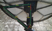
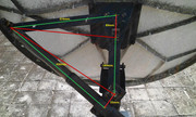
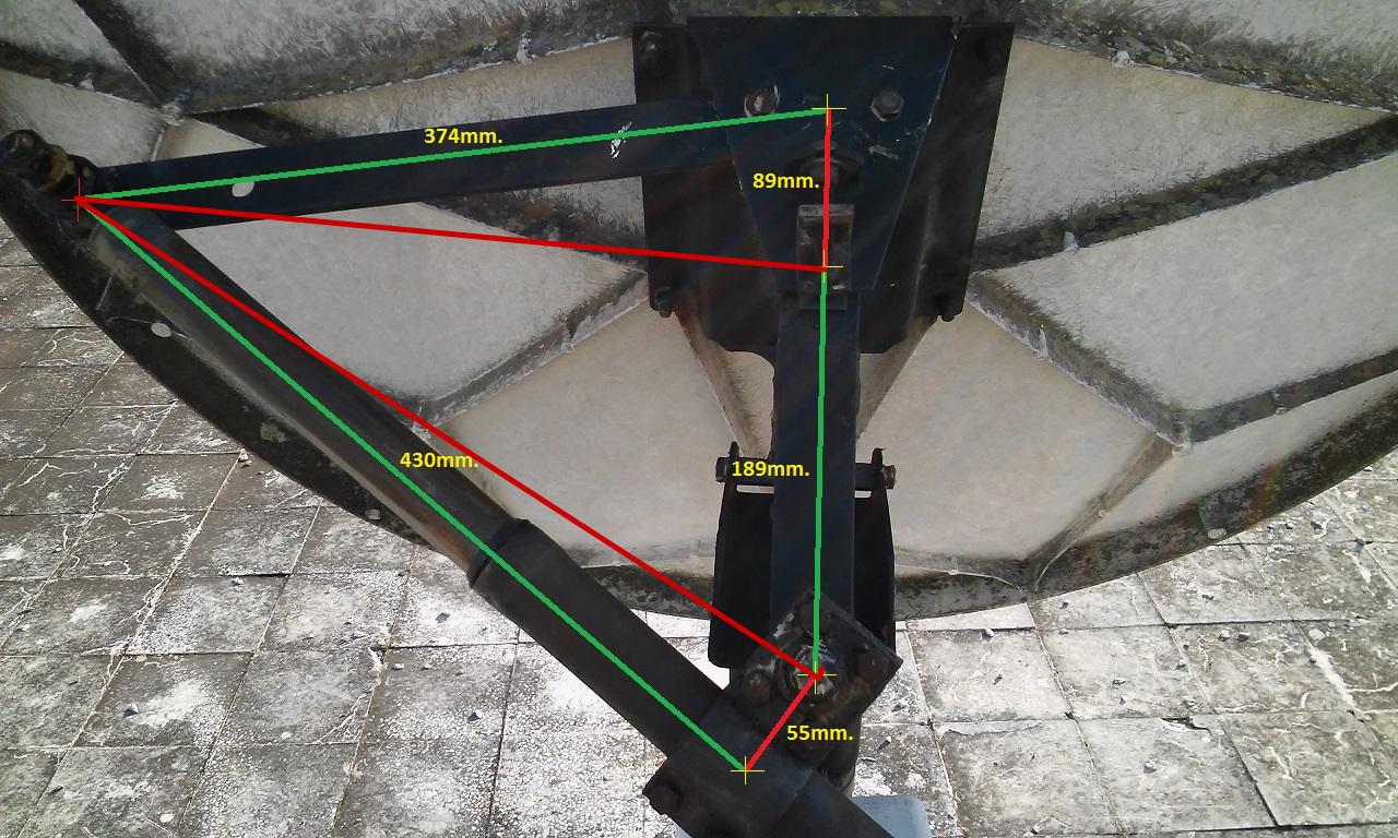
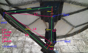
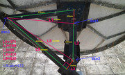
Vorrei queste misure:
Nel piano perpendicolare all'asse di rotazione:
1. distanza T-A: dalla parte superiore T all'asse A (uso un valore positivo per avere l'attuatore sul lato est dell'asse, un valore negativo quando è sul lato ovest);
2. distanza A-BB: dall'asse A al bullone inferiore BB;
3. distanza T-BB(RefSat): dalla parte superiore T dell'attuatore al bullone inferiore BB (sul supporto), quando la parabola è puntata verso il RefSat (una posizione satellitare di riferimento, necessaria per determinare l'angolo della posizione apicale della configurazione dell'attuatore). Si prega di utilizzare un satellite situato all'incirca a sud;
4. distanza B-BB: dalla parte inferiore B dell'attuatore al bullone inferiore BB sul supporto.
Quando c'è una differenza di altezza tra la parte superiore T dell'attuatore e la parte inferiore B dell'attuatore (vedere il disegno satelliteguys), assicurarsi di misurare B-BB ancora nel piano perpendicolare all'asse di rotazione; e misurare anche la distanza 5:
5. H: Differenza di altezza dell'attuatore, tra la parte superiore T e la parte inferiore B. Misurarla perpendicolarmente al piano sopra indicato (il piano perpendicolare all'asse di rotazione), quindi, in altre parole, la misurazione viene effettuata parallelamente all'asse di rotazione.
E naturalmente ho bisogno (anche se in questo caso potrei già calcolarlo da solo):
6. il conteggio degli impulsi del satellite di riferimento.
E naturalmente, quale satellite (longitudine del satellite) avete scelto come RefSat?
Tradotto da:
That is very good news.
I assume this result was with the last calculated file, with the (more) exteme input satellite positions?
As I now had 6 input pulse count values from you, I checked the calculations by taking 4 input values at just the east side, and 4 input values at just the west side. In these cases, I ended 15 to 20 pulse counts from the calculated values for 65W and 90E (at the horizon end of your visible arc).
So this is proof, that indeed it is best to take two of the pulse counts at the extreme sides of your arc.
And that this special calculation method is following the curve for the actuator movement very accurately.
In the meantime I have found (see the posts above), that the +1 or -1 factor is not a constant, but a variable (dependent on the satellite position that the dish/actuator setup is aimed at). I have found a good way to calculate/determine it, so that seems to be solved. The equation now is going back to:
PulseCount = A + factorE * (sqareroot( B + C*cos(UsalsAngle) + D*sin(UsalsAngle) ) ).
I have not determined yet, what is special about the angle at which the swap between +1 and -1 takes place. For that, I would be glad if you indeed can measure some things at your polar mount.
Please look at the picture at the right of post #93:
https://www.digital-forum.it/thread...quesito-matematico.217614/page-5#post-7787986
and/or at the picture added to this post:
https://www.satelliteguys.us/xen/threads/usals-for-buds.168945/page-2#post-4289371
I would want these measures:
In the plane perpendicular to the rotation axis:
1. distance T-A: Top to Axis (I use a positive value for having the actuator at the east side of the axis, a negative value when at the west side);
2. distance A-BB: Axis to Bottom Bolt;
3. distance T-BB(RefSat): from Top of the actuator to Bottom Bolt (on the mount), when the dish is aimed at the RefSat (a reference satellite position, that is needed to determine the angle of the apex position of your actuator setup). Please use a satellite somewhere around due south;
4. distance B-BB: Bottom of actuator to Bottom Bolt at the mount.
When there is a height difference between the Top T of the actuator and the Bottom B of the actuator (see the satelliteguys drawing), be sure to measure B-BB still in the plane perpendicular to the rotation axis, and also measure distance 5:
5. H: Height difference of the actuator, between top T and bottom B. Measure this perpendicular to the above plane (the plane perpendicular to the rotation axis), so in other words the measurement is done parallel to the rotation axis.
And of course I need (though in this case I could already calculate it myself):
6. the pulse count of the Refence satellite.
And of course, what satellite (satellite longitude) longitude did you chose as RefSat?
Translated from:
Ciao,
A33
 senza nulla togliere alle tabelle fornitemi in precedenza da